“OUR KEY PRODUCTS ARE
reinforcing steel bar series products.”
STEEL GRATING, BAR GRATING
At JinDing, we focus on concrete reinforcing steel bar, ribbed steel bar, deformed bar, round or square bar, reinforcing mesh, steel fiber, steel bar grating, angle steel and series steel materials for construction application.
- Home
- Product Center
- Product Center Reinforcing Bar
Reinforcing Steel Bar, Reinforcing Fabric and Rebar Ties
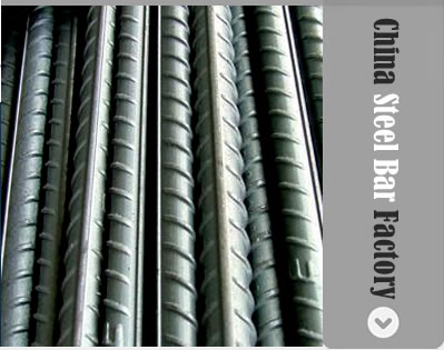
Reinforcing Steel Bar, also called Rebar, is a building material used for reinforcement of concrete structures and various reinforcement works for construction.
Reinforcing bars (rebars) can be either smooth plain or deformed. Hot rolling process with subsequent superficial hardening by heat treatment is popularly used in reinforcing bars manufacture.
We supply Reinforcing Steel Bar of various bar types, sizes, shapes and grades.
Quality: ASTM A706M, ASTM A615 Gr40-60, BS4449:97 Grade 460B, DIN488 BST 500S, CA-50, or equivalent.
Common bar sizes: 8-32mm.
Length: 6-12m.
Packaging: 2 MT bundles.
REINFORCING BAR PRODUCTS
Reinforcement Steel Bar - ASTM A706M Grade
Bar Designation Number with Reinforcing Steel Bar Diameters:
| Bar Designation Number Shown in ASTM A706M (metric equivalent shown in brackets) | Permitted Equivalent Reinforcing Steel Bar Diameter (mm) |
| #4 (13 mm) | 12 |
| #5 (16 mm) | 16 |
| #6 (19 mm) | 20 |
| #8 (25 mm) | 25 |
| #9 (29 mm) | 28 |
| #10 (32mm) | 32 |
| #11 (36 mm) | 36 |
| #14 (43 mm) | 40 |
Uncoated Reinforcing Bar, Deformed
Bar Diameter 12mm and smaller: ASTM A706M Deformed Carbon-Steel Bars with a minimum yield strength of 420 MPa (Grade 60).
Bar Diameter 16mm and above: ASTM A706M Deformed Carbon-Steel Bars with a minimum yield strength of 420 MPa (Grade 60)
Plain round reinforcing bars
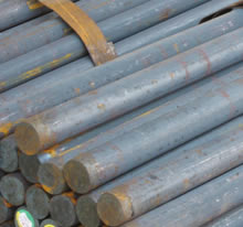
Conform to a minimum yield strength of 420 N/mm² (Grade 60) ASTM A706M.
Hot rolled or cold worked high tensile steel bars shall not be used in the same structural member.
Reinforcement Fabric
Reinforcing fabric of welded steel wire in accordance with ASTM A497.
Tie Wires
Tying wire for steel bar reinforcement is also called Rebar Tie Wire or Bar Ties.
Tie wire 1.6mm diameter (Gauge # 16)
Material: Annealed mild steel wire, complying with AASHTO M32/ASTM A-82 or equivalent.
Dowel Bars
Dowel bars for expansion and construction joints in concrete
Plain round bars, minimum 420 N/mm2 (Grade 60) to ASTM 706M galvanized
Dowel bars are straight, free from burrs or other irregularities and shall have their sliding ends sawn. The sliding half of each dowel bar shall be provided with a plastic cap at least 100mm long, the end 20mm is fitted with a disc of joint filler.
Dowel bars diameter 20mm
Our reinforcing bars are supplied in good quality, tested as following
Samples
Representative samples of reinforcement steel bar and reinforcement fabric are submitted for Engineer approval
Testing
1) In the event that a reinforcement steel sample under test fails to meet the Specification requirements at any time, or the Engineer considers that samples which were presented to him for test were not truly representative, or if it becomes apparent that reinforcement steel which has not been approved has been used on the Works, the Engineer shall instruct the Contractor to break out and remove completely all such sections of the work already constructed using such suspect reinforcement steel.
2) All testing of reinforcement steel bars shall meet the requirements and specification limits of the AASHTO/ASTM/PNS/JIS or any equivalent designation for the particular size, grade and any additional requirements, as approved by the Engineer.
Steel Reinforcement Fabrication, Marks, Storing and Surface
Bending
Bar reinforcement shall be cut and bent to the shapes. Fabrication tolerances shall be in accordance with requirement. All bars shall be bent cold, unless otherwise permitted. Bars partially embedded in concrete shall not be field-bent except as specified.
Hooks and Bend Dimensions
The dimensions of hooks and the diameters of bends measured on the inside of the bar shall be as shown in the contract documents. When the dimensions of hooks or the diameter of bends are not shown, they shall be in accordance with Article 5.10.2 of the AASHTO LRFD Bridge Design Specifications or ACI 318/318R-95, Building Code Requirements for Structural Concrete.
Identification
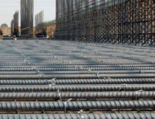
Bar reinforcement shall be shipped in standard bundles, tagged and marked in accordance with the Manual of Standard Practice of the Concrete Reinforcing Steel Institute.
Handling, Storing, and Surface Condition of Reinforcement
Steel reinforcement shall be stored above the surface of the ground on platforms, skids, or other supports and shall be protected from mechanical injury and surface deterioration caused by exposure to conditions producing rust. When placed in the work, reinforcement shall be free from dirt, loose rust or scale, mortar, paint, grease, oil, or other nonmetallic coatings that would reduce bond.
Epoxy coated reinforcement shall not be permitted in the Works.
Reinforcement shall be free from injurious defects such as cracks and laminations. Bonded rust, surface seams, surface irregularities, or mill scale shall not be cause for rejection, provided the minimum dimensions, cross-sectional area, and tensile properties of a hand wire-brushed specimen meet the physical requirements for the size and grade of steel specified.
Placing and Fastening Reinforcement Steel Bars with Supports
General
Steel reinforcement shall be accurately placed and firmly held in position during the placing and consolidation of concrete. Bars shall be tied at all intersections around the perimeter of each mat and at not less than 600 mm centers or at every intersection, whichever is greater, elsewhere. Bundled bars shall be tied together at not more than 1,800 mm centers.
If uncoated welded wire fabric is shipped in rolls, it shall be straightened into flat sheets before being placed.
Support Systems
Reinforcing steel shall be supported in its proper position by use of precast concrete blocks, wire bar supports, supplementary bars, or other approved devices.
Such reinforcing supports or devices shall be of such height and placed at sufficiently frequent intervals so as to maintain the distance between the reinforcing steel and the formed surface or the top surface of deck slabs within 6 mm of that indicated in the contract documents.
Platforms for the support of workers and equipment during concrete placement shall be supported directly on the forms and not on the reinforcing steel.
Precast Concrete Blocks
Precast concrete blocks shall have a compressive strength not less than that of the concrete in which they are to be embedded. The face of blocks in contact with forms for exposed surfaces shall not exceed 50 mm x 50 mm in size and shall have a color and texture that will match the concrete surface. When used on vertical or sloping surfaces, such blocks shall have an embedded wire for securing the block to wire or, when the weight (mass) of the reinforcing is sufficient to firmly hold the blocks in place, a groove in the top of the block may be used.
Wire Bar Supports
Wire bar supports, such as ferrous metal chairs and bolsters, shall conform to industry practice as described in the Manual of Standard Practice of the Concrete Reinforcing Steel Institute. Such chairs or bolsters which bear against the forms for exposed surfaces shall be either:
Class 1-Maximum Protection (Plastic Protected); or
Class 2, Type B-Moderate Protection (Stainless Steel Tipped) for which the stainless steel conforms to ASTM A493, Type 430.
Adjustments
Non-prestressed reinforcement used in post-tensioned concrete shall be adjusted or relocated during the installation of prestressing ducts or tendons, as required to provide planned clearances to the prestressing tendons, anchorages, and stressing equipment, as approved by the Engineer.
Splicing of Bars
General
All reinforcement shall be furnished in the full lengths specified in the contract documents, unless otherwise permitted or where splices are shown on the Drawings. Except for splices specified in the contract documents and splices for 16 mm diameter or smaller bars, splicing of bars shall not be permitted without written approval by the Engineer. Splices shall be staggered as far as possible.
Lap Splices
Lap splices shall be of the lengths specified in the contract documents. If not specified in the contract documents, the length of lap splices shall be in accordance with Article 5.11.5.3.1 or Article 5.11.5.5.1 of the AASHTO LRFD Bridge Design Specifications, or as approved by the Engineer.
In lap splices, the bars shall be placed and tied in such manner as to maintain the minimum distance to the surface of the concrete shown in the contract documents.
Welded Splices
Welded splices of reinforcing bars shall be used only if detailed in the contract documents or if authorization is made by the Engineer in writing. Welding shall conform to the ANSI/AWS D1.4 Structural Welding Code Reinforcing Steel, and the contract documents.
Welded splices shall not be used with reinforcement conforming to ASTM A1035/A1035M.
Mechanical Splices
Mechanical splices shall be used only if pre-approved or detailed in the contract documents or authorized in writing by the Engineer. Such mechanical splices shall develop in tension or compression, as required, at least 125 percent of the specified yield strength of the bar being spliced.
When requested by the Engineer, up to two field splices out of each 100, or portion thereof, placed in the work and chosen at random by the Engineer, shall be removed by the Contractor and tested by the Engineer for compliance to the required 125 percent of the specified yield strength of the bars being spliced.
Splicing of Welded Wire Fabric
Sheets of welded wire fabric shall be spliced by overlapping each other sufficiently to maintain a uniform strength and shall be securely fastened at the ends and edges. The edge lap shall not be less than one mesh in width plus 50 mm.
OUR PRODUCTS
» Rebar Cages
» Steel Bar Gratings
» Reinforcing Bar
» Rebar Couplers
» Steel Reinforcement Mesh
» Concrete Reinforcement Steel Bar
» Concrete Reinforcing Mesh
» Ribbed Steel Bar Welded Mesh
» Reinforcing Steel PC Strand
» Round Steel Bar
» Hot Rolled Ribbed Steel Bar
» Deformed Steel Bar
» Hot Rolled Steel Plate
» Square Steel Bar
» Cold Rolled Steel Bar
» H Beam Steel
» Channel Steel Bar
» U Channel Steel Bar
» I-Beam Steel
» Steel Bar Supports
» High Chairs Wire Spacer
» Reinforcing Steel Bar Chair
» Slab Bolsters/ Beam Bolsters
» Plastic / Polyethylene Rebar Supports
» Equal Angle Steel
» Angle Steel Bar
» Spiral PC Wire
» Steel Fiber
» Steel Bar Welding Machine
» Deformed Reinforcing Steel Bar Weight
» Low Cobalt Stainless Steel Bar
» Formwork Rib Lathe
